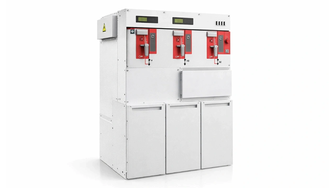

A substation bus bar arrangement is the layout of substation equipment designed to maintain supply continuity, protection, and switching, most importantly by creating alternate power paths in case the main path fails or needs maintenance. If substation equipment is the hardware, bus bar arrangement is the software that makes it all function together reliably.
Without a proper bus bar arrangement, a substation can't reliably perform its basic functions: changing voltage level, protecting against faults, switching supply, and above all, maintaining continuity of supply. In today's world, sustained power interruption isn't something most operations can tolerate.
Let's cover the basics of what a bus bar arrangement actually is, why it exists, and which schemes are commonly used at different voltage levels.
What Functions Does a Substation Perform?
A substation performs four core functions: changing voltage level (stepping up or down), providing fault protection through circuit breakers, switching supply as needed, and maintaining continuity of supply.
Circuit breakers trip during abnormal fault conditions to protect the system, and the substation also handles routine switching operations and fault detection. Among these, supply continuity is arguably the most critical function, since sustained outages simply aren't acceptable in modern power systems. A bus bar arrangement is what enables all four of these functions to work together reliably.
What Problem Led to the Development of Bus Bar Arrangements?
Bus bar arrangements were developed to solve a specific reliability problem: older circuit breakers like oil and air-blast breakers needed frequent maintenance, and that maintenance required interrupting supply entirely.
Consider a generating station connected through a step-up transformer to a switchyard using an oil circuit breaker, with disconnectors on both ends. During normal operation, everything stays closed and supply continues uninterrupted. The moment that breaker needs maintenance, though, the entire section has to be shut down, breaking supply continuity, exactly the function a substation is supposed to guarantee.
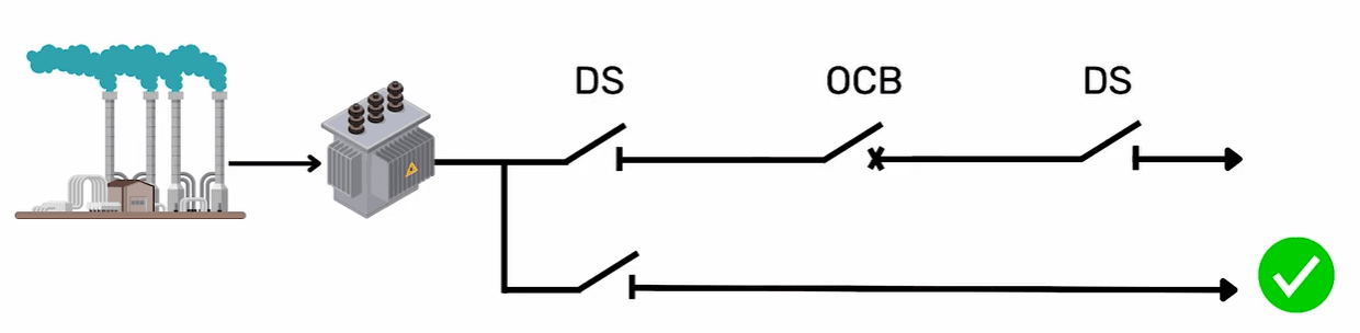
One early workaround was tapping an additional disconnector to provide an alternate supply path while the main breaker was under maintenance, then shifting the load back once maintenance finished. This wasn't a robust long-term solution on its own, but it illustrates exactly why bus bar arrangements were born: substations needed a designed way to keep power flowing even when one path had to go offline.
Modern circuit breakers require far less frequent maintenance today, but the underlying importance of bus bar arrangement hasn't gone away. It remains one of the most consequential design decisions in substation engineering.
What is a Bus Bar Arrangement, in Simple Terms?
A bus bar arrangement is the layout of substation equipment designed to create an alternate path for power flow, so supply continuity is maintained even if the main path fails or requires maintenance.
A simple example is the double bus bar scheme: if one bus bar fails or needs maintenance, a second bus bar serves as backup, keeping supply uninterrupted. That backup-path principle is the core idea behind every bus bar scheme.
What Other Names is Bus Bar Arrangement Known By?
Bus bar arrangement is also referred to as circuit arrangement, switching arrangement, circuit configuration, or bus bar scheme, all describing the same underlying concept.
If someone mentions "switching arrangement" or "circuit arrangement" in a substation design context, they're referring to the same thing as bus bar arrangement.
What Are the Common Bus Bar Schemes?
The main bus bar schemes used in substation design are the single bus bar scheme, double bus bar scheme, main and transfer bus scheme, and one-and-a-half breaker scheme, each serving a different balance of cost, flexibility, and supply security.
Selection depends on what the substation needs most: operational flexibility, high supply security, or cost efficiency, and different schemes serve each priority differently. There's no universal standard dictating which scheme must be used for a given voltage level; selection is based on the standard practice and accumulated experience of each utility or country's governing body, not a fixed rule.
Which Bus Bar Scheme is Used at Each Voltage Level?
Bus bar scheme selection generally follows voltage level, with simpler schemes at lower voltages and more robust schemes at higher voltages, though this reflects common practice, not a mandatory standard.
Voltage Level | Commonly Used Scheme(s) |
36 kV and below | Single bus bar scheme |
145 kV | Main and transfer scheme, double bus bar scheme |
245 kV | Double bus bar scheme |
400 kV | Double bus bar scheme, one-and-a-half breaker scheme |
800 kV | One-and-a-half breaker scheme |
These voltage ratings follow IEC standards, though the exact scheme chosen still comes down to each utility's own standard practice and experience. In medium voltage switchgear, you'll typically only see single or occasionally double bus bar arrangements; the more complex schemes are largely reserved for high and extra-high voltage substations.
Do These Schemes Apply to Both AIS and GIS Substations?
Yes, bus bar schemes apply to both air-insulated substations (AIS) and gas-insulated substations (GIS); the scheme itself is independent of whether air or gas provides the insulation medium.
These schemes are typically represented visually through single line diagrams (SLDs), which is why reading an SLD accurately is a foundational skill for understanding any substation's bus bar arrangement at a glance.
FAQ
Is there a fixed rule for which bus bar scheme to use at a given voltage?
No. While certain schemes are commonly associated with certain voltage levels, there's no standard that mandates a specific scheme for a specific voltage. Selection depends on each utility's priorities and standard practice.
Why is bus bar arrangement compared to "software" in a substation?
Because it's what coordinates how the physical equipment, the "hardware," actually functions together to deliver protection, switching, and supply continuity. Without the right arrangement, even good equipment can't maintain reliable operation.
What's the simplest example of a bus bar arrangement improving reliability?
A double bus bar scheme, where a second bus bar acts as backup if the primary one fails or needs maintenance, is the clearest simple example of how bus bar arrangement maintains supply continuity.
Do modern circuit breakers reduce the need for bus bar arrangements?
Modern breakers need far less frequent maintenance than older oil or air-blast breakers, but bus bar arrangement remains essential for handling faults, planned maintenance, and overall supply security, not maintenance frequency alone.
Are bus bar schemes the same for air-insulated and gas-insulated substations?
Yes, the same schemes, single bus bar, double bus bar, main and transfer, and one-and-a-half breaker, apply to both AIS and GIS substations; the insulation medium doesn't change the underlying arrangement logic.
Conclusion
A bus bar arrangement is what allows a substation's equipment to actually deliver on its core promise: reliable voltage transformation, protection, switching, and above all, uninterrupted supply.
The specific scheme, single bus bar, double bus bar, main and transfer, or one-and-a-half breaker, is chosen based on voltage level, required flexibility, supply security needs, and each utility's own standard practice, not a single fixed rule. For anyone moving into substation design, understanding these schemes thoroughly is essential.
For the full visual walkthrough of each scheme, watch the complete video on the TheElectricalGuy YouTube channel.
Watch the Youtube Video

About Author
Gaurav Joshi
Gaurav started his career on the floor of the electrical industry — not in a classroom. Working across Siemens and Schneider Electric, he saw firsthand how wide the gap was between what colleges teach and what the industry actually needs.
So he did something about it.
Today, he's built a global community of 300,000+ engineers and professionals across YouTube and beyond — and TheElectricalGuy Academy is where that knowledge lives in its most structured, practical form.