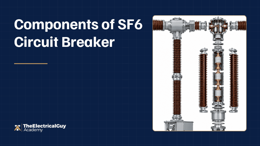
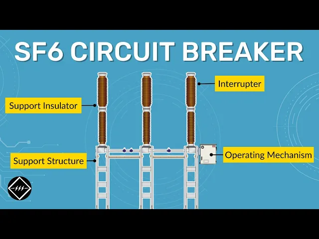
An SF6 circuit breaker is built from four main components: the interrupter, which actually breaks the current; the support insulator, which maintains safe clearance to ground; the operating mechanism, which opens and closes the contacts; and the support structure, which holds the entire assembly at a safe height. Every circuit breaker above 52 kV in high and extra-high voltage substations most commonly uses this SF6-based design (however few manufacturers now have HV & EHV vacuum circuit breakers as well) .
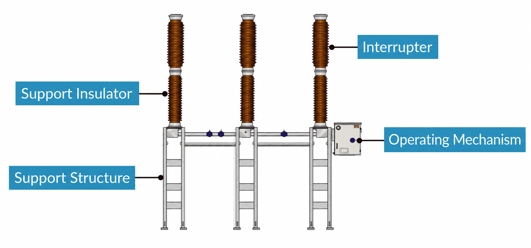
A circuit breaker, in simple terms, is a mechanical device capable of making, carrying, and breaking both normal current and rated fault current for a specified time. Making that possible above 52 kV requires four specific components working together, each with its own distinct job.
What is the Interrupter and How Does It Work?
The interrupter is the top portion of the breaker where actual current interruption happens, using main contacts for normal current and arcing contacts for fault current, with SF6 gas quenching the resulting arc.
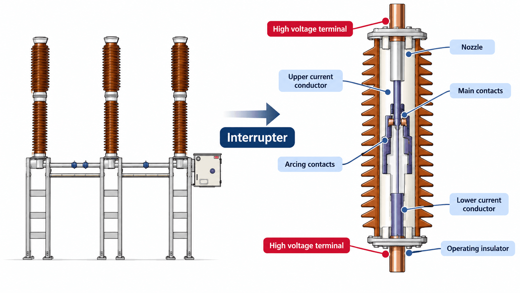
Main contacts — carry the rated normal current continuously, built with comparatively low resistance material.
Arcing contacts — carry fault current specifically, since fault current is extremely high; made from different material suited to that different purpose.
Nozzle — focuses SF6 gas directly onto the arc during interruption, enabling smooth arc quenching.
Insulating enclosure — the entire interrupter assembly sits inside porcelain or silicon composite insulators, with an incoming and outgoing connection wiring the breaker in series with the system.
How Many Interrupters Does an SF6 Breaker Need at Different Voltage Levels?
A single interrupter per phase is sufficient up to and including 245 kV, but higher voltage levels require multiple interrupters connected in series per phase, a design called a multi-break circuit breaker.
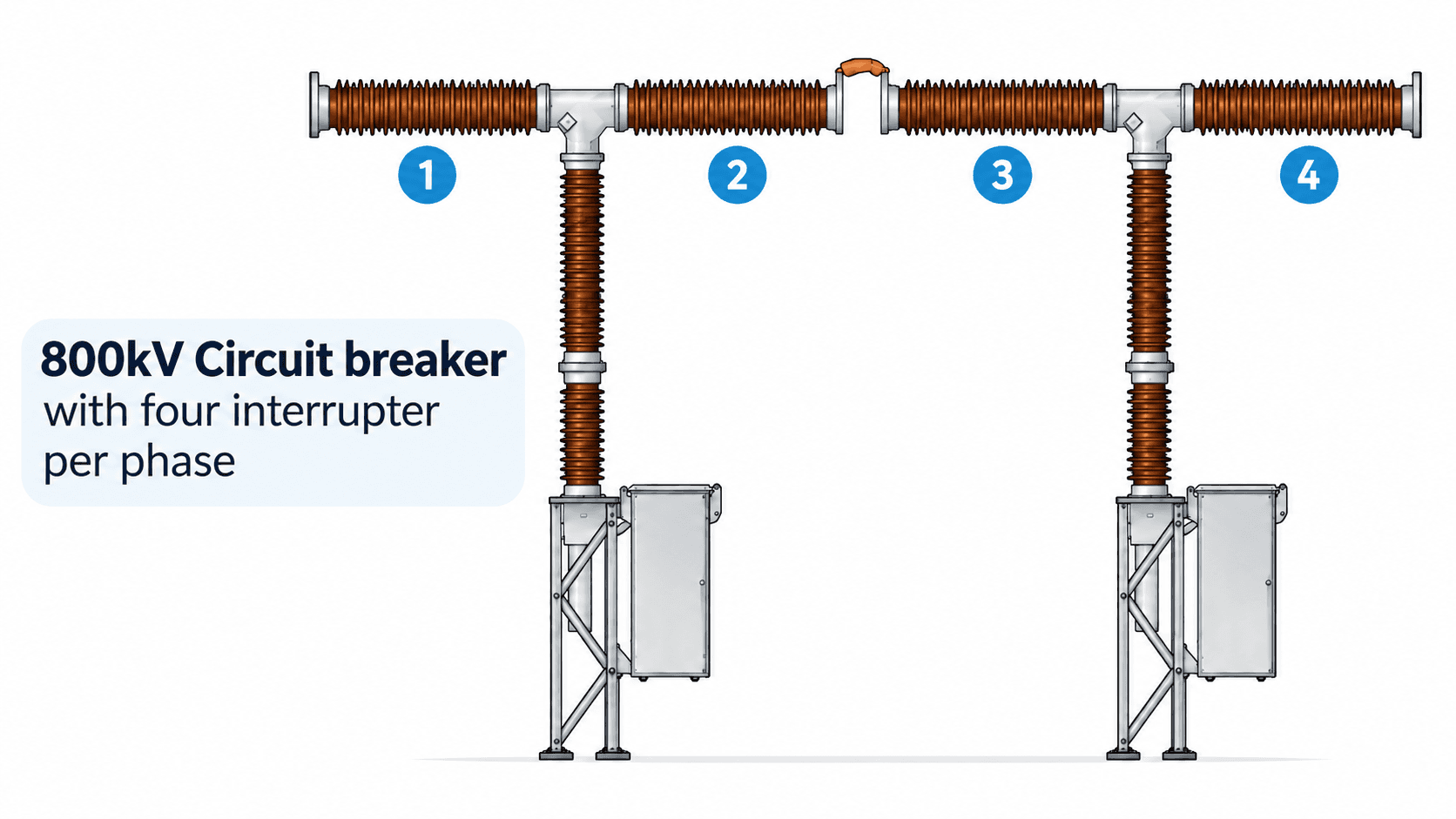
72.5 kV to 245 kV — one interrupter per phase (single-break).
400 kV — two interrupters in series per phase, meaning six interrupters total across all three phases.
800 kV (extra-high voltage) — four interrupters in series per phase, meaning twelve interrupters total across all three phases.
Any breaker using more than one interrupter per phase is classified as a multi-break circuit breaker, a design necessary at higher voltages where a single interrupter can't reliably break the current or maintain sufficient clearance.
What is the Support Insulator For?
The support insulator maintains sufficient clearance between the live high voltage terminal and ground, protecting anyone working near the breaker's operating mechanism.
Made from porcelain or silicon composite material, it's a hollow insulator through which the operating rod passes, with its own insulating medium inside. Its core function is safety: guaranteeing a safe working clearance for personnel operating or maintaining the breaker.
What is the Operating Mechanism and How Does It Work?
The operating mechanism is the complete mechanical assembly responsible for opening and closing the breaker's contacts, using two dedicated springs, one for closing and one for tripping, in most modern designs.
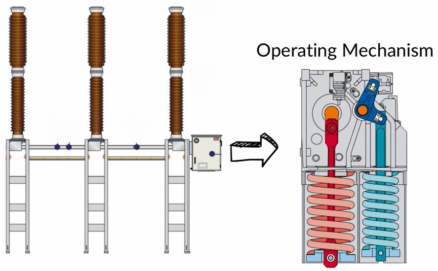
Circuit breakers have historically used hydraulic and pneumatic mechanisms as well, but spring-based mechanisms are now the standard. Separating the contacts requires significant force delivered at high speed, since a slow opening defeats the entire purpose of interruption. The closing spring and tripping spring each handle their respective function.
What Else is Housed in the Operating Mechanism Box?
Beyond the springs and operating rod, the mechanism box, also called the control box or marshalling box, houses the breaker's complete control circuitry: MCBs, contactors, and the electrical logic needed for correct operation, collectively referred to as the breaker's secondary schematic.
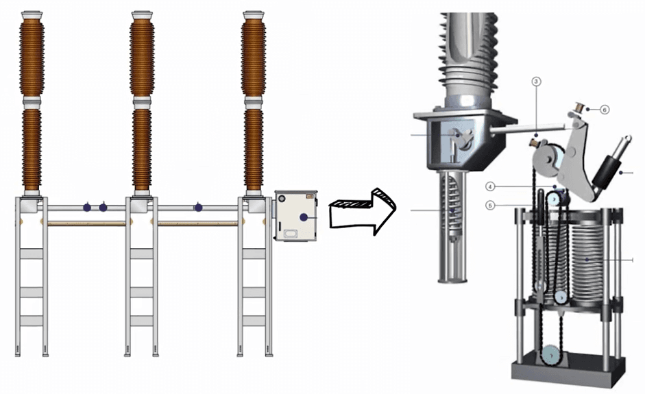
The operating rod runs from this mechanism box through the hollow support insulator to the interrupter itself, physically linking the control logic to the actual current-interrupting contacts.
What are the Base Frame and Support Structure For?
The base frame holds the three poles, interrupters, and support insulators assembled together, while the support structure lifts and holds that entire assembly at a safe height above ground.
The base frame is the horizontal steel structure everything is mounted and screwed onto. Since the live terminals carry high voltage (145 kV, 245 kV, and beyond), the assembly can't sit directly on the ground; the support structure, made of steel, maintains the necessary safe clearance between the live parts and ground level.
FAQ
What are the four main components of an SF6 circuit breaker?
The interrupter, support insulator, operating mechanism, and support structure. The interrupter breaks current, the support insulator maintains safe clearance, the operating mechanism drives the opening and closing action, and the support structure holds the whole assembly at height.
Why do main contacts and arcing contacts use different materials?
Because they serve different functions: main contacts carry normal current continuously and need low resistance, while arcing contacts specifically handle the much higher fault current, requiring a material suited to withstand that stress.
Why does a 400 kV circuit breaker need two interrupters per phase?
Because a single interrupter isn't sufficient to reliably break the current or maintain adequate clearance at that voltage level. Using two interrupters in series distributes the interruption duty and required clearance across both breaks.
What is the secondary schematic of a circuit breaker?
It refers to the electrical control circuitry, including MCBs, contactors, and control logic, housed inside the operating mechanism's control box (also called the marshalling box), which governs how and when the breaker opens and closes.
Why can't the circuit breaker assembly sit directly on the ground?
Because the live terminals operate at high voltage, and a safe clearance must be maintained between live parts and ground to protect personnel. The support structure provides that necessary height and clearance.
Conclusion
An SF6 circuit breaker's four components work together as a single system: the interrupter does the actual work of breaking normal and fault current using SF6 gas to quench the arc, the support insulator keeps live parts a safe distance from ground, the operating mechanism drives fast, forceful contact separation, and the support structure holds everything at a safe working height. Understanding each part's specific role is the foundation for reading any high or extra-high voltage circuit breaker's design correctly.
If you want to understand the control circuitry and secondary schematics of a circuit breaker in full depth, explore the Circuit Breaker Control Schematics Masterclass.
Watch the Youtube Video

About Author
Gaurav Joshi
Gaurav started his career on the floor of the electrical industry — not in a classroom. Working across Siemens and Schneider Electric, he saw firsthand how wide the gap was between what colleges teach and what the industry actually needs.
So he did something about it.
Today, he's built a global community of 300,000+ engineers and professionals across YouTube and beyond — and TheElectricalGuy Academy is where that knowledge lives in its most structured, practical form.