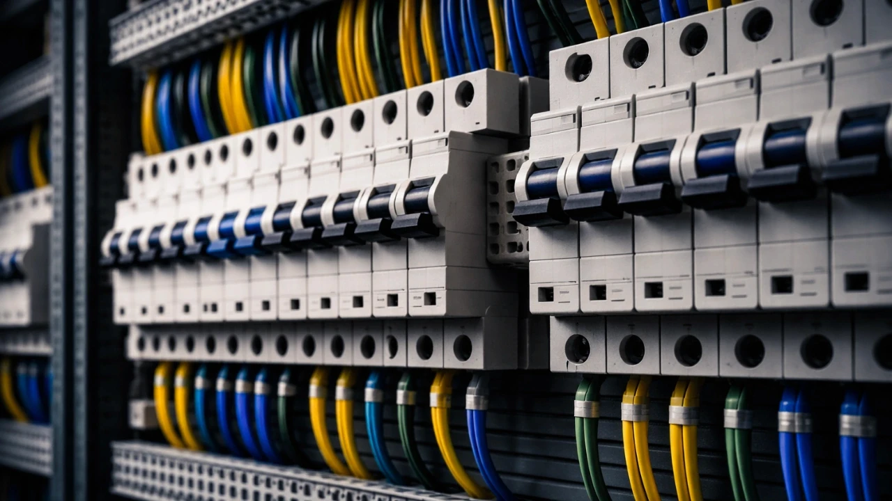

Reading an electrical schematic gets manageable with five steps: understand the components used in the circuit, get familiar with symbols and the title block, learn the designer's stated assumptions, understand the drawing's structure and power flow direction, and follow the power flow as it continues across multiple pages. Skipping the first step, understanding components, is the single most common reason engineers stay stuck.
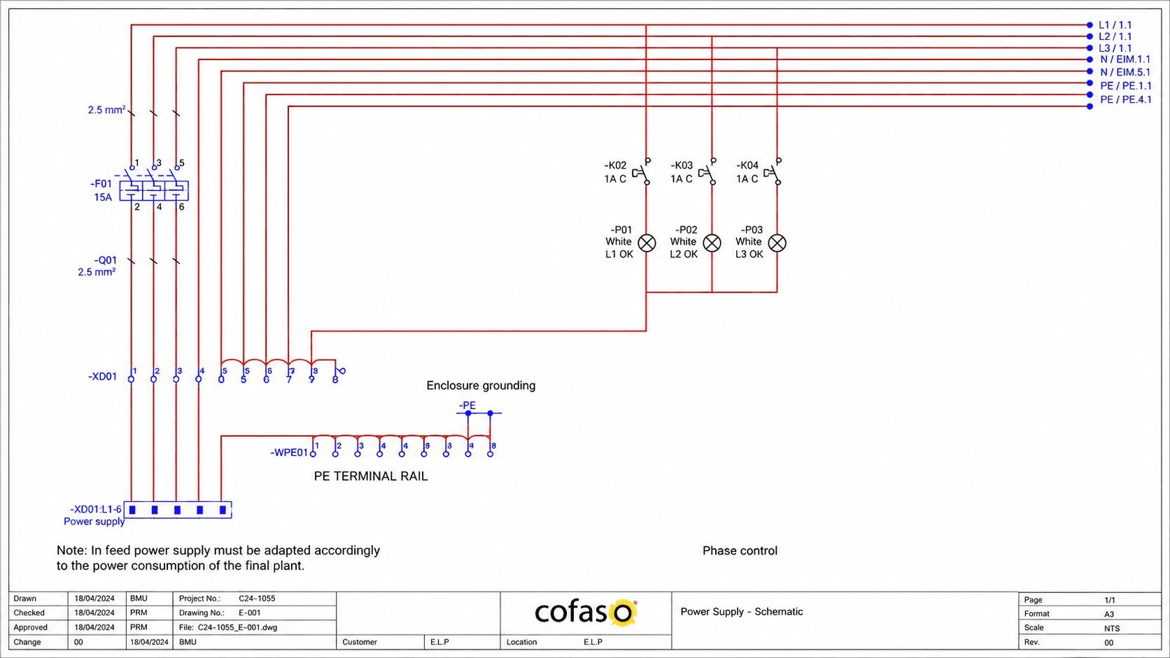
When I first saw the control schematic of a high voltage circuit breaker, it looked like a puzzle someone had scrawled on paper, or a maze with no way in. I was convinced I'd never understand it. What changed things wasn't more staring at the drawing; it was breaking it down systematically, step by step, until the puzzle started unfolding into something logical.
These five steps are the same ones I've used to build a dedicated course on circuit breaker control schematics. Here's the starting point, in plain terms.
What is an Electrical Schematic, Really?
An electrical schematic is a map of a circuit's connections, junctions, and interlocks, the same way a map turns an unfamiliar jungle into something navigable.
Sent into a jungle with no map, you'd wander without knowing where the paths, junctions, or destination are. Given a map of that same jungle, navigation becomes straightforward. Open the control wiring of a switchgear panel without a schematic, and you're looking at the same jungle: wiring with no visible logic. The schematic is what turns that wiring into something you can actually follow.
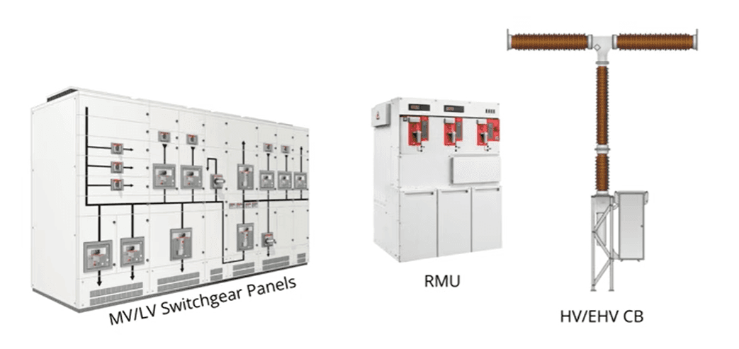
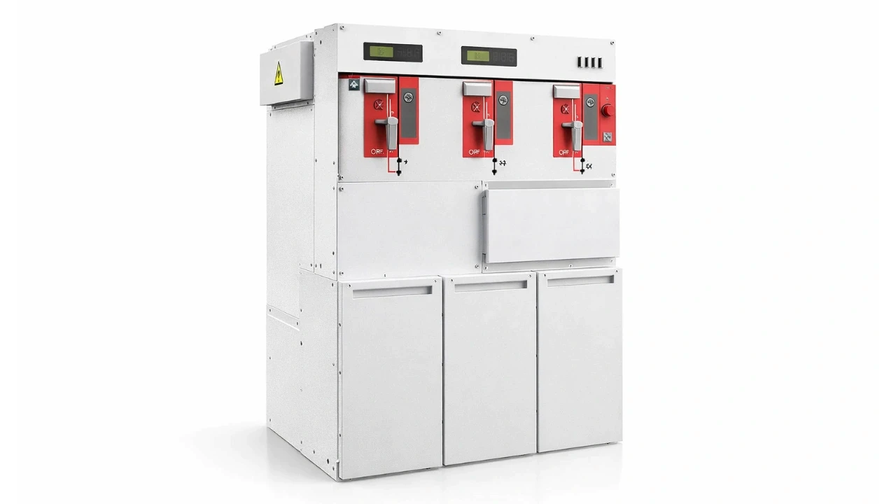
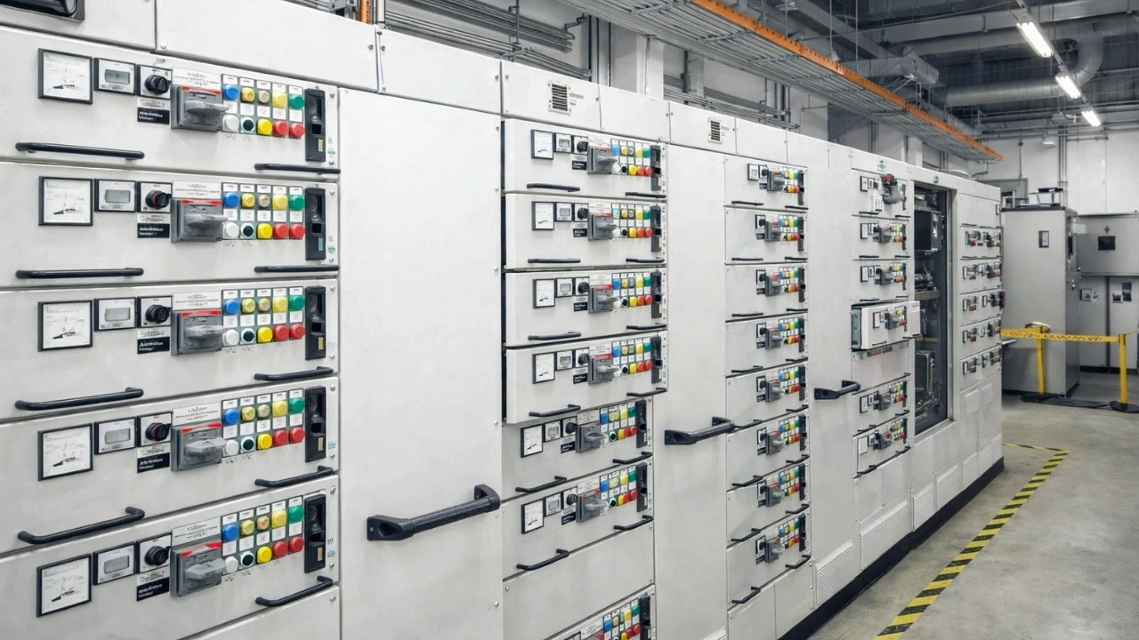
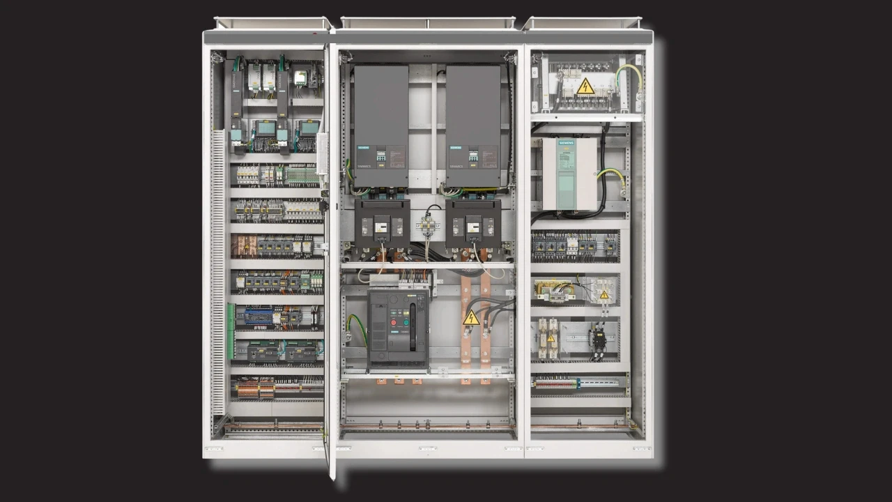
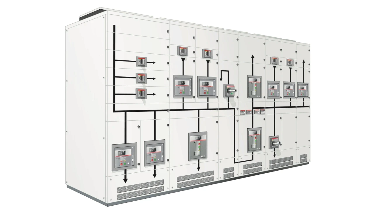
Electrical schematics show up widely: in medium and low voltage switchgear, ring main units, high and extra-high voltage circuit breakers, and industrial automation and PLC logic. The application is broad, but the reading method stays the same.
Step 1 — Why Should You Understand the Components First?
Understanding the components used in a control circuit, contactors, relays, fuses, push buttons, selector switches, has to come before you even open the schematic, because the rest of the reading process depends entirely on it.
Knowing why each component is used, and how it functions, is what makes the rest of the drawing readable. Take a contactor, one of the most common components in electrical logic: if you don't know how it operates or what its construction looks like, understanding its role in the schematic becomes nearly impossible. This step is the one most people skip, jumping straight into the drawing instead, and it's exactly why they stay confused.
Step 2 — How Do You Read Symbols, the Title Block, and Designations?
Getting familiar with standard symbols, the drawing's title block, and component designations is what lets you identify what each part of the schematic actually represents.
What Does the Title Block Tell You?
The title block, typically found at the bottom of the drawing, tells you what the drawing is about: whether it's a closing circuit, tripping circuit, PLC wiring, or auxiliary circuit, along with the customer and project name. Reading this first sets the context for everything else on the page.
Why Are Standard Symbols Used Instead of Component Images?
Standard symbols represent components instead of actual images, since real component appearances vary by manufacturer and using images would make drawings impossible to fit on a page. The full set of symbols used in a specific drawing is typically listed in the bill of materials or abbreviations table, usually at the front or back of the drawing set. Skipping this step means you'll have no idea what a given symbol represents once you're inside the drawing.
What Do Component Designations Mean?
Components aren't labeled in plain language on the drawing; they use standard designations instead, K1 for the first contactor, K2 for the second, and so on. You'll also commonly see A1 and A2 marked on a contactor, indicating the coil terminals where supply connects. This is exactly where Step 1 pays off: without understanding what a contactor's coil actually is, A1 and A2 mean nothing.
Step 3 — Why Do You Need to Understand the Designer's Assumptions?
Understanding the assumptions stated by the designer is essential because a schematic alone can't tell you whether a component is shown in its energized or de-energized state, unless that assumption is explicitly stated.
A contactor's contacts change position when energized. Looking at a drawing without knowing the stated default condition, you can't tell whether what you're seeing is the resting state or the energized state. Designers typically state this explicitly, for example, "all contactors are shown in de-energized condition", meaning the shown position is the contact's default, and it will change once energized.
The same logic applies to a drawn circuit breaker: whether it's shown open or closed by default needs to be stated as an assumption too. These assumptions are usually noted at the front or back of the drawing set, and skipping them leaves you guessing why a given contact is drawn open or closed.
Step 4 — How Do You Read the Schematic's Structure and Power Flow?
Understanding the drawing's overall structure, and the direction power flows through it, tells you how to actually follow the circuit from source to load.
A full drawing set opens with title and project detail pages, then splits the circuit across multiple dedicated pages, since a complete system rarely fits on one sheet. One page might show a load break switch's wiring, another the circuit breaker's. For AC supply, identify the power source and follow the path, generally left to right. For DC supply, especially in common European drafting practice, the positive line runs across the top and the negative line across the bottom, with circuits drawn top to bottom between them, not bottom to top.
Step 5 — How Do You Follow Power Flow Across Multiple Pages?
Following power flow across pages means tracking the page and column reference numbers printed alongside the wiring, which tell you exactly where a connection continues from or to.
Since a single page can't show an entire system, the power flow continues from page to page, and each page uses a numbering system to reference that continuity.
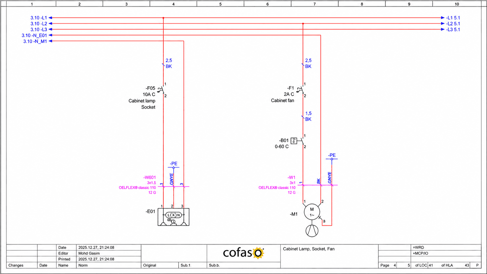
A notation like "3.10" on page four means the incoming connection continues from page 3, column 10, referencing the standard column numbering (typically 1 through 10) printed across the top of each page, similar to spreadsheet column references. Missing this step is one of the most common points of confusion, since a supply that looks unexplained on one page is usually just continuing from a bus bar shown on a previous page.
What Common Mistakes Do People Make Reading Schematics?
The most common mistake is skipping the fundamentals, jumping straight into the drawing without first understanding components, symbols, and stated assumptions, which guarantees confusion regardless of how carefully the rest of the drawing is studied.
Skipping component fundamentals — trying to read a schematic without first understanding how a contactor, relay, or fuse actually works.
Ignoring the title block — starting to trace wiring before knowing what circuit the page even represents.
Missing the stated assumptions — misreading a contact's state because the default condition (energized vs. de-energized) was never checked.
Losing track of page continuation — assuming a supply appears from nowhere instead of tracing the page/column reference back to its source.
FAQ
What's the single most important first step in reading an electrical schematic?
Understanding the components used in the circuit, contactors, relays, fuses, and similar devices, before opening the drawing at all. Everything else depends on that foundation.
Why do electrical schematics use symbols instead of actual component images?
Component appearances vary by manufacturer, and using real images would make drawings too complex to fit on a page. Standard symbols keep drawings consistent and readable regardless of manufacturer.
How do you know if a contact is shown in its energized or de-energized state?
The designer states this explicitly as an assumption, usually at the front or back of the drawing set, such as "all contactors are shown in de-energized condition." Always check this before interpreting contact positions.
Do all electrical schematics flow in the same direction?
No. AC-supply schematics are generally followed from the power source outward, typically left to right, while DC schematics, especially in common European drafting practice, are read top to bottom, with positive on top and negative on the bottom.
How do you follow a circuit that continues across multiple pages?
Look for the page and column reference numbers printed alongside the wiring, e.g. "3.10" means the connection continues from page 3, column 10, letting you trace the connection back to its actual source.
Conclusion
These five steps, understanding components, reading symbols and the title block, checking the designer's stated assumptions, understanding structure and power flow direction, and tracking power flow across pages, turn an electrical schematic from a confusing maze into a readable map. This is a starting point, not a finish line; real fluency comes from repeatedly practicing these steps on real drawings.
If you want to go deeper specifically on circuit breaker control schematics, explore the Circuit Breaker Control Schematics Masterclass.
Watch the Youtube Video


About Author
Gaurav Joshi
Gaurav started his career on the floor of the electrical industry — not in a classroom. Working across Siemens and Schneider Electric, he saw firsthand how wide the gap was between what colleges teach and what the industry actually needs.
So he did something about it.
Today, he's built a global community of 300,000+ engineers and professionals across YouTube and beyond — and TheElectricalGuy Academy is where that knowledge lives in its most structured, practical form.