
Earthing systems are classified into five main types: TN-C, TT, TN-C-S, TN-S, and IT, each defined by how the source neutral and exposed equipment parts connect to earth. The choice between them directly determines how fast a fault clears and how safe the installation is when something goes wrong.
Two buildings can operate at the same voltage level, yet their safety level can differ greatly. The difference often comes down to which earthing system was used. On the panels and installations I've worked on, a poorly designed earthing arrangement is exactly what turns a simple insulation fault into a serious shock hazard.
You can install the best cables, the best circuit breakers, and the best electrical panel, and still end up with a dangerous installation if the earthing design is weak. Before covering each system, it helps to decode the IEC classification letters first.
How Does IEC Classification Work for Earthing Systems?
IEC classification uses two or three letters to describe how the power source and the exposed equipment parts connect to earth.
The first letter describes the source's connection to earth:
T (Terra) — source neutral directly connected to earth
I (Isolated) — source isolated from earth, or connected through impedance
The second letter describes how exposed conductive parts connect to earth:
T — exposed parts connected to a local earth electrode
N — exposed parts connected to the supply neutral conductor
Additional letters describe the conductor arrangement:
C (Combined) — neutral and protective earth share one conductor (PEN)
S (Separate) — neutral and protective earth remain separate conductors
A combination like TN-C-S isn't a random label, it directly describes how grounding works and how the protective conductors are arranged. Once you can read these codes, identifying any earthing system becomes straightforward.
What is the TN-C Earthing System?
The TN-C system is considered one of the least safe earthing arrangements because it has no dedicated protective conductor.
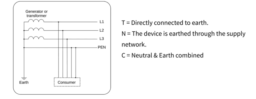
Decoded: T means the source neutral is directly earthed, N means equipment bodies connect to the supply neutral, and C means neutral and protective earth are combined into one shared conductor, the PEN. Using one conductor instead of two reduces installation cost, which is why utilities sometimes use this arrangement in distribution networks.
The risk shows up if the PEN conductor breaks upstream, sometimes far from the actual installation. Equipment bodies can then become live. Consider a small workshop connected through a TN-C supply: a loose connection develops in the PEN conductor near the pole, and metal parts inside the workshop, motor housings, panel enclosures, machine casings, may now sit at phase voltage. Touching that equipment body completes the circuit and causes a shock.
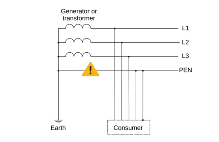
Because of this risk, pure TN-C systems are rarely allowed inside buildings. They may appear in distribution networks, but not within installations themselves.
What is the TT Earthing System?
The TT system improves safety over TN-C by giving each installation its own local earth electrode instead of relying on a shared conductor.
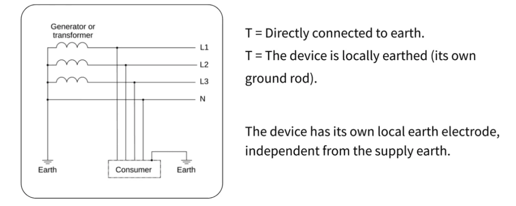
The source neutral remains earthed (first letter T), and exposed conductive parts connect to a separate local earth electrode (second letter T). Each installation gets its own earth pit, and equipment bodies connect directly to it. A rural farmhouse supplied by a utility line with phase and neutral conductors, and its own earth pit for all equipment bodies, is a typical example.
The challenge is that during a fault, current has to return through the soil to the transformer neutral. Soil resistance is usually high, so the fault loop impedance is high too, and the resulting fault current may stay too small to trip an MCB quickly. This is why TT systems depend heavily on RCCB protection, the RCCB detects leakage current and disconnects the circuit fast, regardless of soil resistance. If the RCCB fails or gets bypassed, safety drops significantly.
Compared with TN-C, TT removes the combined-conductor risk, but it depends heavily on RCCB operation, soil resistivity, and earth electrode quality.
What is the TN-C-S Earthing System?
The TN-C-S system offers a practical balance between safety and cost by combining the conductor near the source and separating it inside the installation.
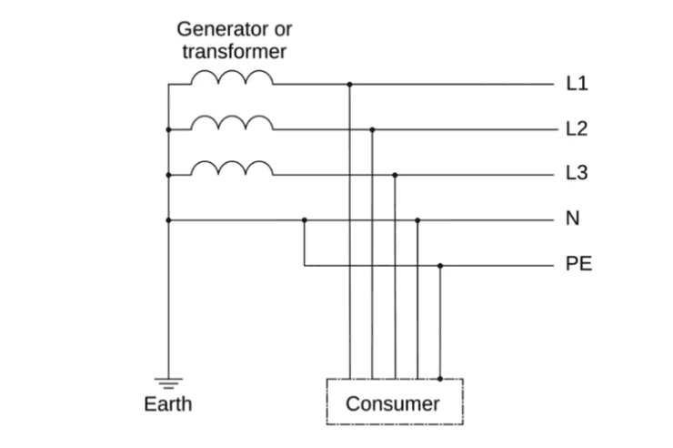
Decoded: T means the source neutral is earthed, N means equipment connects to the supply neutral, C means the conductor is combined for part of the system, and S means it separates afterward. From the transformer to the service entry, a PEN conductor is used; inside the building, neutral and earth become separate conductors. This arrangement is called Protective Multiple Earthing (PME), and it's very common in urban residential buildings.
Inside the installation, equipment bodies connect to a dedicated protective earth conductor, so fault current returns through a low-impedance metallic path, which lets protective devices trip quickly, faster than TT for fault clearing.
One concern remains: if the PEN conductor breaks before the separation point, dangerous voltage can appear in the installation. TN-C-S still depends partly on upstream conductor integrity, but it remains one of the most widely used earthing systems today.
What is the TN-S Earthing System?
The TN-S system is considered the safest arrangement among TN systems because neutral and protective earth are fully separate from the transformer itself.
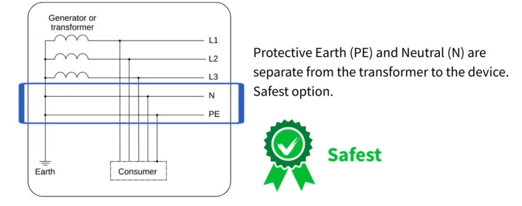
There's no combined PEN conductor anywhere in the network. From the transformer secondary winding, one conductor carries neutral current and another serves as protective earth. Because the conductors stay separate, the risk of combined-conductor failure disappears entirely, and fault current returns through a dedicated low-impedance path, letting protective devices operate faster and more reliably. This significantly reduces touch-voltage risk.
For this reason, TN-S systems are common in:
Large industrial plants
Hospitals
Data centers
Sensitive control installations
The drawback is cost: TN-S needs an additional conductor from source to load, which adds up over long distances. Despite that, it offers excellent safety and electromagnetic performance.
What is the IT Earthing System?
The IT system keeps the source isolated from earth, which lets the supply continue operating even after a single phase-to-earth fault.
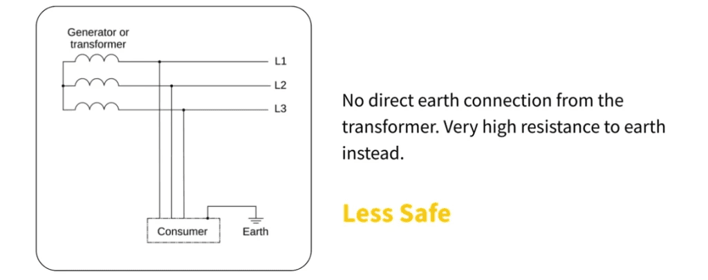
In this configuration, the source is isolated from earth, sometimes connected through high impedance instead of direct grounding, while exposed conductive parts remain connected to earth electrodes. When a single phase-to-earth fault occurs, the system doesn't trip immediately, and the supply continues running, which is exactly why it's valuable in critical applications:
Hospitals and operating rooms
Mines
Critical process industries
Because a first fault won't trip the supply, IT systems require additional monitoring. Special insulation monitoring devices detect the first fault so maintenance teams can locate and fix it before a second fault occurs. Due to this added complexity, IT systems aren't common in general distribution networks they mainly appear where uninterrupted power matters most.
How Do the Earthing Systems Compare?
Earthing System | Conductor Arrangement | Fault Current Path | Safety Level | Common Applications |
TN-C | Neutral and earth combined in one PEN conductor | Returns through the combined PEN conductor | Lowest among TN systems | Utility distribution networks |
TT | Neutral from supply, local earth electrode at installation | Returns through soil to transformer neutral | Safer than TN-C, but depends on RCCB | Rural houses, small installations |
TN-C-S | Combined PEN conductor first, then separate N and PE | Returns through low-impedance metallic earth path | Good balance of safety and cost | Urban residential installations |
TN-S | Neutral and protective earth fully separate from source | Returns through dedicated protective conductor | Highest among TN systems | Hospitals, industries, data centers |
IT | Source isolated from earth, exposed parts earthed | Fault current limited due to isolation | Best for supply continuity | Hospitals, mines, critical processes |
FAQ
Which earthing system is safest?
TN-S is generally considered the safest among TN systems because it has no combined conductor risk anywhere in the network. IT systems offer a different kind of safety, prioritizing supply continuity in critical applications where an unplanned trip is more dangerous than the fault itself.
Why does the TT system depend so heavily on RCCBs?
Because fault current has to return through soil, which has high resistance, the resulting fault current is often too small to trip a standard MCB quickly. An RCCB detects leakage current directly instead of relying on fault current magnitude, so it disconnects the circuit fast regardless of soil conditions.
What's the danger of a broken PEN conductor?
If the PEN conductor breaks upstream in a TN-C or TN-C-S system, before the separation point, equipment bodies can become live at phase voltage, creating a serious shock hazard for anyone touching them.
Why don't IT systems trip on the first earth fault?
The source is isolated from earth, so a single phase-to-earth fault doesn't create a complete fault loop large enough to trip protection immediately. This lets critical supplies, like operating rooms, keep running while the fault is located and fixed.
Why is TN-C-S so widely used despite its PEN conductor risk?
It balances cost and safety well using one combined conductor from the transformer to the service entry keeps installation costs down, while separating neutral and earth inside the building gives a low-impedance fault path for fast, reliable protection.
Conclusion
Earthing design determines how fault current flows in a system and how quickly protective devices respond. Ranked from least to most robust for general safety: TN-C carries the highest risk due to its combined conductor, TT is safer but depends on RCCB and soil conditions, TN-C-S offers a balanced solution widely used in installations, TN-S is the best standard practice for safety and performance, and IT is best suited for continuity of supply in critical applications.
Earthing isn't simply about driving a rod into the ground. It defines the entire fault path in an electrical system, and a well-designed earthing system is what ensures faults clear quickly and safely.
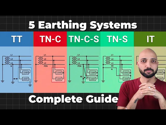
For a clearer practical walkthrough of each system, watch the detailed video on the TheElectricalGuy YouTube channel.
Watch the Youtube Video

About Author
Gaurav Joshi
Gaurav started his career on the floor of the electrical industry — not in a classroom. Working across Siemens and Schneider Electric, he saw firsthand how wide the gap was between what colleges teach and what the industry actually needs.
So he did something about it.
Today, he's built a global community of 300,000+ engineers and professionals across YouTube and beyond — and TheElectricalGuy Academy is where that knowledge lives in its most structured, practical form.