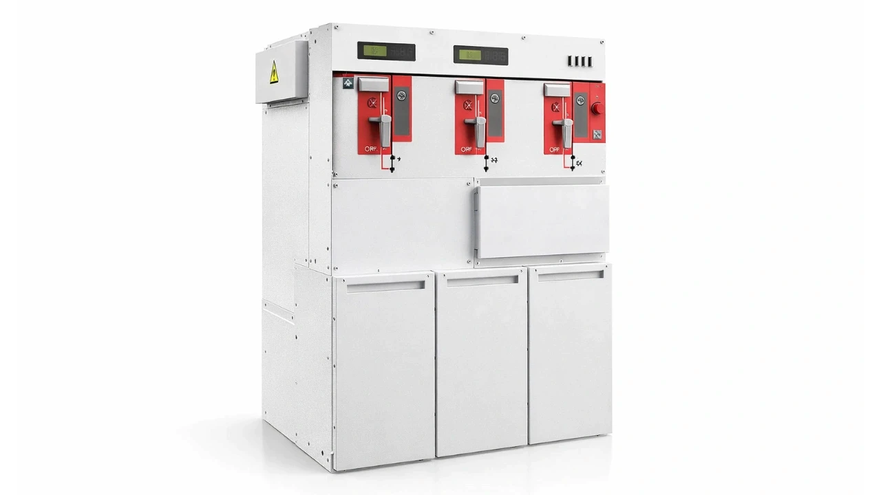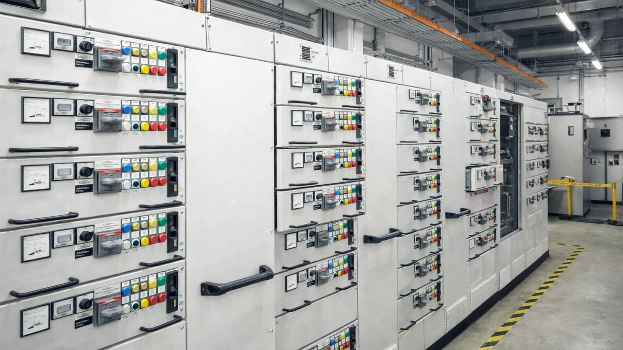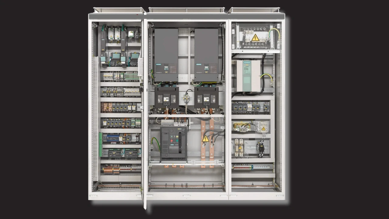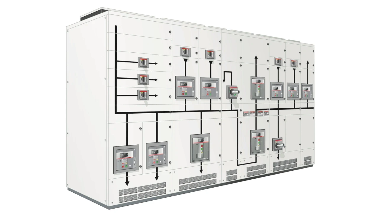

The 10 key switchgear parameters are rated voltage, rated normal current, rated short-circuit breaking current, rated short-time withstand current, rated peak withstand current, CT/VT accuracy class, internal arc classification (IAC), IP rating, insulation levels, and CT/VT burden. Getting any one of these wrong is usually why a switchgear fails on site, not the manufacturer.
Most electrical engineers can name the switchgear manufacturer on a panel. Very few can tell you why a switchgear actually fails. In most of the cases I've seen on site, it comes down to one thing: someone selected the wrong parameter.
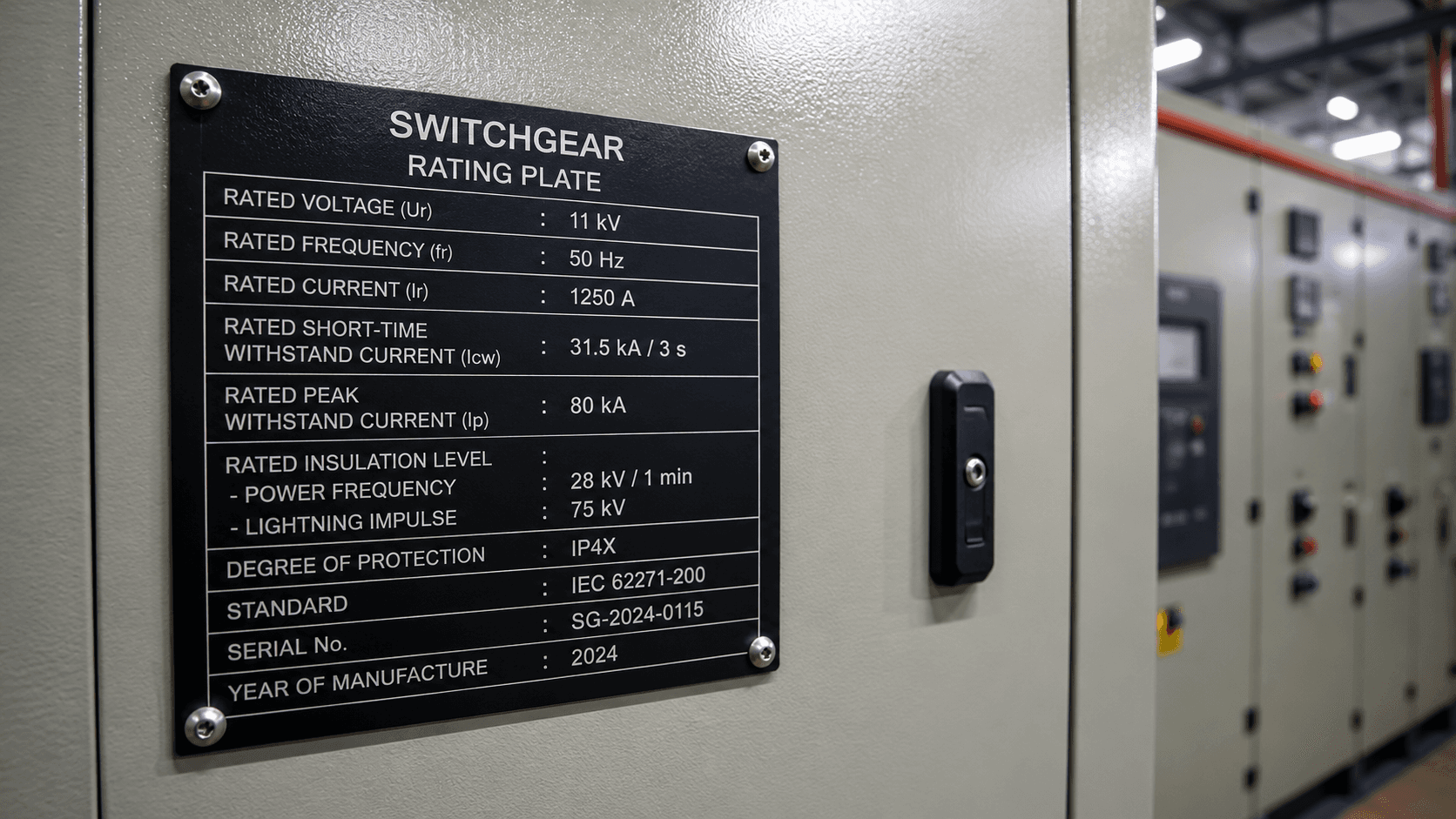
These 10 parameters apply across low, medium, and high voltage switchgear. Let's go through each one, and what goes wrong when you get it wrong.
What is the Rated Voltage of a Switchgear?
Rated voltage is the maximum voltage at which the switchgear is designed to operate continuously. It is not the same as your system voltage, and mixing the two up is a common mistake.
In India and other countries that follow IEC standards, the rated voltage of the equipment should be one step above the actual system voltage. For example, an 11 kV system needs switchgear rated at 12 kV, the next standard rating above it.
Selecting equipment rated at exactly the system voltage might work fine during normal operation. The problem shows up during transient switching surges or overvoltage events, which will happen over the equipment's life. The insulation of underrated equipment can fail under that stress. The rule stays simple: always select rated voltage above the actual system voltage.
What is the Rated Normal Current of a Switchgear?
Rated normal current is the maximum continuous current the switchgear can carry without exceeding its temperature limits.
Selecting a rating higher than your load current sounds straightforward, but the ambient temperature correction factor is where people go wrong. IEC standards generally specify current ratings at an ambient of 40°C, but many installations, especially enclosed substation buildings or hot outdoor sites, can reach 45°C or higher.
Higher ambient temperature reduces the switchgear's actual current-carrying capacity. An 800A rated panel running at 45°C ambient might only carry around 760A in practice. Run it at full 800A anyway, and it runs hot: insulation and connections degrade over time, leading to premature failure.
Always check the manufacturer's temperature derating factor, and upsize accordingly in hot environments.
What is the Rated Short-Circuit Breaking Current?
Rated short-circuit breaking current is the maximum fault current the circuit breaker inside the switchgear can safely interrupt.
When a short circuit occurs, a very large current, say 25 kA or 31.5 kA, flows through the system instantly. The breaker must open and stop that current. If your system can deliver 25 kA of fault current but the switchgear is only rated for 20 kA breaking capacity, the breaker cannot interrupt it. It tries to open, the internal arc cannot extinguish, and the result is catastrophic failure: an explosion, an arc flash, extremely dangerous to anyone nearby.
This is why short-circuit breaking current is the single most important parameter from a safety standpoint. Standard values you'll typically see: 16 kA, 20 kA, 25 kA, 31.5 kA, 40 kA, 50 kA, and 63 kA. Always run the short-circuit calculation before finalizing the breaker rating, there's no room to compromise here.
What is the Rated Short-Time Withstand Current & Peak withstand current?
Rated short-time withstand current is the fault current the entire switchgear assembly, not just the breaker, can carry without damage for a specified duration, typically 1 or 3 seconds.
This is different from breaking current. Breaking current is what the circuit breaker can interrupt. Short-time withstand current matters because protection relays take a brief moment to detect a fault and send a trip signal. During that window, fault current flows through the bus bars, CTs, VTs, and connections, and they all need to survive it mechanically and thermally.
If the short-time withstand rating is lower than the actual fault current, even for that brief pre-trip window, you risk bus bar distortion, connection failure, or a bus bar explosion from electromagnetic forces. A common medium-voltage standard value is 25 kA for 3 seconds, matched to the system's fault level.
What is the Rated Peak Withstand Current (Making Current)?
Rated peak withstand current, denoted IP or "making current," is the highest instantaneous current a switchgear can withstand when it closes onto an existing fault. It's the most commonly overlooked of the 10 parameters.
At the very first instant of a fault, the current doesn't start from zero, a DC offset in the system creates an initial asymmetric peak well above the RMS value. This peak can reach up to 2.5 times the RMS fault current at 50 Hz, and up to 2.6 times at 60 Hz. A 25 kA RMS fault level can therefore produce an initial peak as high as 62.5 kA.
This peak matters most when a breaker closes back onto an existing fault, which happens with autoreclosing schemes designed to ride through transient faults that clear on their own. When that happens, every connected component, not only the breaker, must withstand that peak. Engineers routinely check short-circuit and withstand currents but skip this one, don't.
Why Do CT and VT Accuracy Classes Matter?
CT and VT accuracy class defines how much measurement error is permissible, and metering-class and protection-class instrument transformers are not interchangeable.
Instrument transformers step high voltage and current down to safe, measurable secondary values, typically 1A or 5A for CTs and 110V for VTs. Metering CTs use classes such as 0.1, 0.2, 0.2S, and 1, the lower the number, the less error allowed, which is why 0.2S-class CTs are used for billing-accuracy metering. Use a coarser class where fine metering accuracy is needed, and your readings, and your billing, will be wrong.

Protection CTs have their own separate set of accuracy classes. Connecting a metering-class CT to a protection relay, or vice versa, means the system won't perform as intended. The rule is simple: metering CTs for meters, protection CTs for relays, never mix them.
What is Internal Arc Classification (IAC) and Why Does It Matter?
Internal Arc Classification (IAC) rates how safely a switchgear contains and redirects the energy released during an internal arc fault, protecting personnel nearby.
An internal arc fault happens inside the panel due to insulation failure, contamination, or even small animals getting in, and it's one of the most dangerous events in any switchgear installation. It releases enormous energy, pressure, heat, and hot gases within milliseconds. Without proper containment design, panel doors can blow open and hot gases can be ejected toward the operator, with potentially fatal results.
A typical rating looks like IAC AFLR 21kA 1s. The letter A means the switchgear is accessible only to authorized personnel, indoors or in a control room. Letter B means the switchgear is installed where the general public may be present, common with ring main units placed on footpaths in cities. FLR indicates the sides tested: front, lateral, rear.
One important clarification: an IAC rating doesn't mean an internal arc will never happen. It means that if it does happen, the product is tested to contain it safely. Wherever operators or the public are regularly present, verify this rating against the test certificate, it's non-negotiable.
What is IP Rating and How Do You Select It?
IP (Ingress Protection) rating tells you how well a switchgear enclosure resists solid particles and liquid, and it should be matched to the installation environment, not chosen by default.
The IP code has two digits: the first for solid-particle protection (0–6), the second for liquid protection (0–8). IP54, for example, means protected against dust ingress and protected against water splashing from any direction.
An indoor switchgear in a clean control substation room may only need IP31 or IP54. Outdoor installations, or dusty environments like cement plants, steel plants, or mining sites, typically need IP54, IP55, or higher. Select a rating lower than the environment demands, and dust and moisture will enter the panel over time, leading to insulation tracking, surface discharge, and eventually a fault.
Why Do Insulation Levels Need an Altitude Correction?
Insulation levels, specifically rated lightning impulse withstand voltage and power frequency withstand voltage, are defined for a standard altitude of 1,000 m, and installations above that need a correction.
Power frequency withstand voltage is tested with AC at 50 Hz for one minute, checking basic insulation strength during normal steady-state operation. Impulse withstand voltage tests the switchgear against very short, high-magnitude spikes from lightning strikes or switching surges lasting only microseconds but reaching several times the operating voltage. For a 12 kV rated switchgear, the standard power frequency withstand is 21 kV, and the impulse withstand is 75 kV peak.
Here's the part most engineers miss: those standard values apply at 1,000 m altitude. Higher altitude means higher moisture content in the air, which reduces its dielectric properties, this mainly affects air-insulated switchgear, since gas-insulated designs keep everything sealed inside insulating gas.
Installing 145 kV-class equipment at 2,000 m, for instance, may require stepping up to 245 kV-class equipment instead, based on the altitude correction calculation. Skip this correction, and you may have effectively underrated your insulation.
What is CT/VT Burden and Why Does It Get Overlooked?
CT/VT burden is the total load connected to the secondary winding of a current or voltage transformer, expressed in VA, and exceeding the rated burden silently damages measurement accuracy.
A CT rated for 15 VA can supply a maximum of 15 VA to everything connected to its secondary: protection relays, meters, wiring resistance, and more, without exceeding its accuracy class. In practical installations, multiple devices often share the same CT secondary. If their combined burden exceeds the CT's rated burden, accuracy suffers because the CT saturates early, and the impact shows up in relay and meter readings.
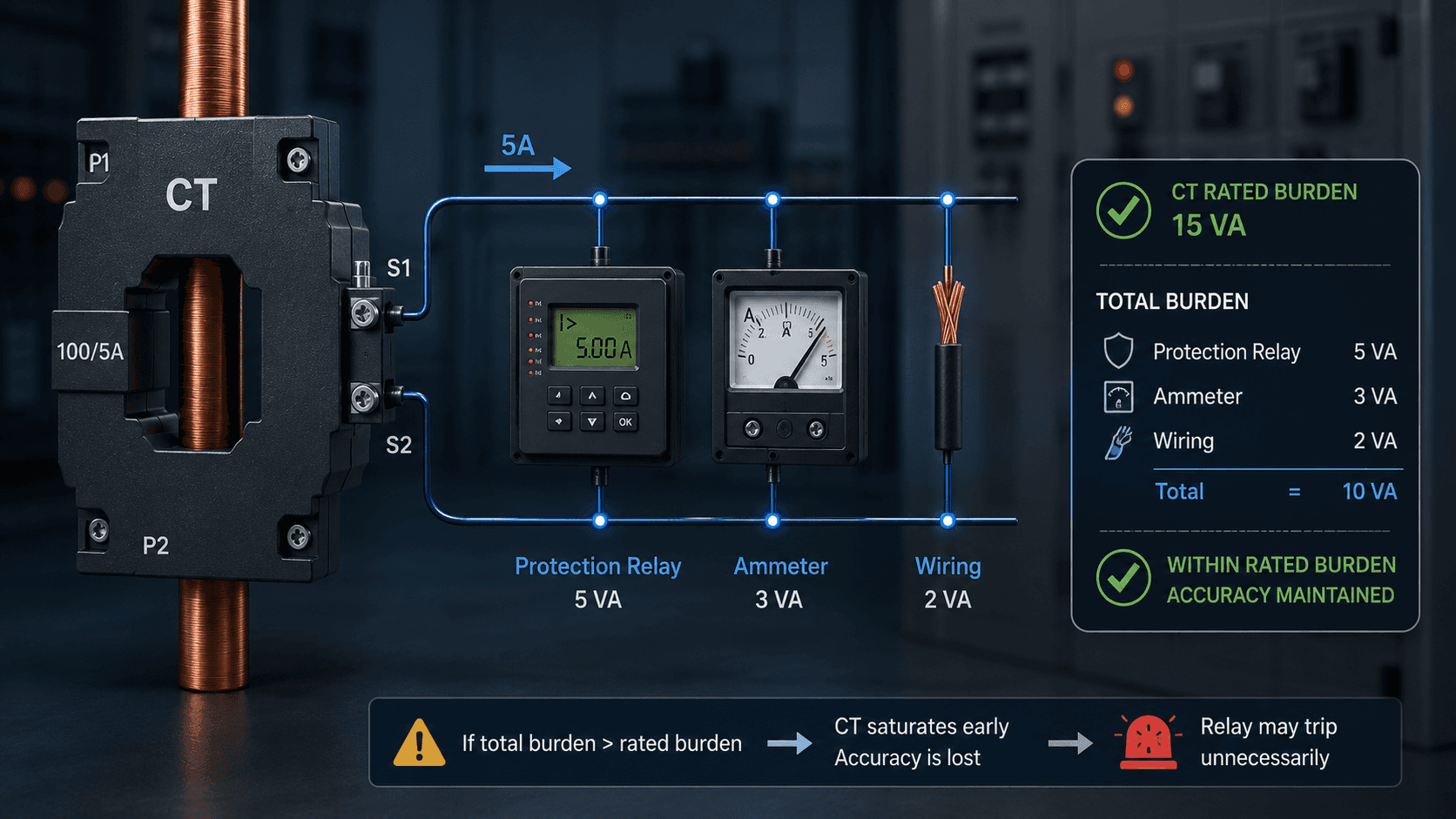
The tricky part: you usually won't notice until a relay starts tripping unnecessarily. Manufacturers guarantee accuracy class only at the rated burden. The fix is to calculate your actual burden requirement first, then select a CT or VT with about 10–15% margin above it. Going too high isn't ideal either, an oversized burden rating makes the transformer unnecessarily bulky and more expensive.
Quick-Check List - All 10 Switchgear Parameters
Use this as a specification checklist every time you review a switchgear datasheet:
Rated voltage — one step above your system voltage
Rated normal current — account for ambient temperature derating
Short-circuit breaking current — must equal or exceed your system fault level
Short-time withstand current — bus bars must survive the relay clearance time
Peak withstand current — often forgotten, but the mechanical forces bend bus bars
CT/VT accuracy class — metering and protection cores are not interchangeable
Internal arc classification (IAC) — your personnel protection certificate
IP rating — match it to the installation environment
Insulation levels — check the altitude correction factor
CT/VT burden — calculate total connected burden, keep it within the rated margin
FAQ
What's the difference between short-circuit breaking current and short-time withstand current?
Breaking current is what the circuit breaker itself can interrupt. Short-time withstand current is what the entire switchgear assembly, bus bars included, can carry without damage during the brief window before the breaker trips.
Why is the peak withstand current higher than the RMS fault current?
A DC offset at the first instant of a fault creates an asymmetric peak that can reach up to 2.5 times the RMS value at 50 Hz, mainly relevant when a breaker closes onto an existing fault through autoreclosing.
Does a higher IAC rating mean an internal arc will never happen?
No. An IAC rating means that if an internal arc does occur, the switchgear is tested to contain and direct the energy away from personnel safely, not that the arc is prevented from happening at all.
Why does altitude affect switchgear insulation levels?
Standard insulation values are defined for 1,000 m altitude. Higher altitude increases moisture in the air, which lowers its dielectric strength, mainly affecting air-insulated switchgear, so equipment installed higher up often needs a higher insulation class.
What happens if CT burden exceeds the rated value?
The CT saturates earlier than designed, degrading measurement accuracy in ways you typically won't notice until a protection relay starts tripping unnecessarily.
Conclusion
These 10 parameters, rated voltage, rated current, short-circuit breaking current, short-time withstand current, peak withstand current, CT/VT accuracy class, internal arc classification, IP rating, insulation levels, and CT/VT burden, are what actually separate a switchgear that performs reliably from one that fails prematurely or dangerously. Most failures I've seen on site trace back to one of these being overlooked, not to the manufacturer.
Treat this as a specification checklist on every switchgear datasheet you review.
For the full walkthrough with real panel examples, watch the complete video on the TheElectricalGuy YouTube channel.
Watch the Youtube Video

About Author
Gaurav Joshi
Gaurav started his career on the floor of the electrical industry — not in a classroom. Working across Siemens and Schneider Electric, he saw firsthand how wide the gap was between what colleges teach and what the industry actually needs.
So he did something about it.
Today, he's built a global community of 300,000+ engineers and professionals across YouTube and beyond — and TheElectricalGuy Academy is where that knowledge lives in its most structured, practical form.