
What Is Inside the Low Voltage Compartment of MV Switchgear?
Quick Answer: The low voltage compartment is the control and protection section of medium voltage switchgear. It houses protection relays, meters, indication lamps, annunciators, and selector switches, and operates below 1000V using current transformers (CTs), voltage transformers (VTs), and an auxiliary DC supply (commonly 110V or 220V DC). It controls how the breaker is monitored, protected, and operated.
On a 36kV panel I've worked on, the cable, breaker, and busbar compartments all sit at 36kV — but the section operators actually touch every day runs at a fraction of that. That section is the low voltage compartment, and it's where protection, indication, monitoring, and switching are managed. Get this part wrong and even the most expensive breaker is useless. So let me walk you through what's inside it and why it matters.
Why Is It Called the Low Voltage Compartment?
It's called the low voltage compartment because everything inside it operates below 1000V, even though the switchgear itself runs at medium voltage.
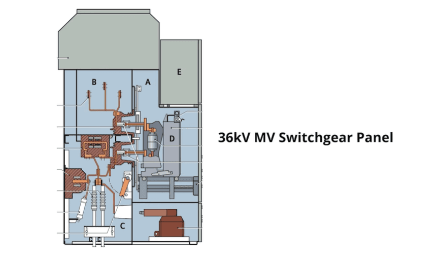
In a 36kV panel, the cable compartment, breaker chamber, and busbar compartment all carry 36kV. One section does not — it runs at low DC levels such as 110V DC, 220V DC, or 48V DC. Because of that, it is called the low voltage compartment. Some engineers also call it the metering and relay chamber. (I'll stay with low voltage compartment throughout.)
The reason is practical. You cannot build a relay or meter that sits directly on 36kV — it would be enormous and unsafe. So engineers use instrument transformers to step voltage and current down to safe values, and the low voltage devices work off those. The exact operating voltage changes with the project and customer requirement, but the purpose stays the same.
Where Is the Low Voltage Compartment Located in the Panel?
In most MV switchgear panels, the low voltage compartment sits at the top, so operators can reach relays, meters, and indication lamps easily.
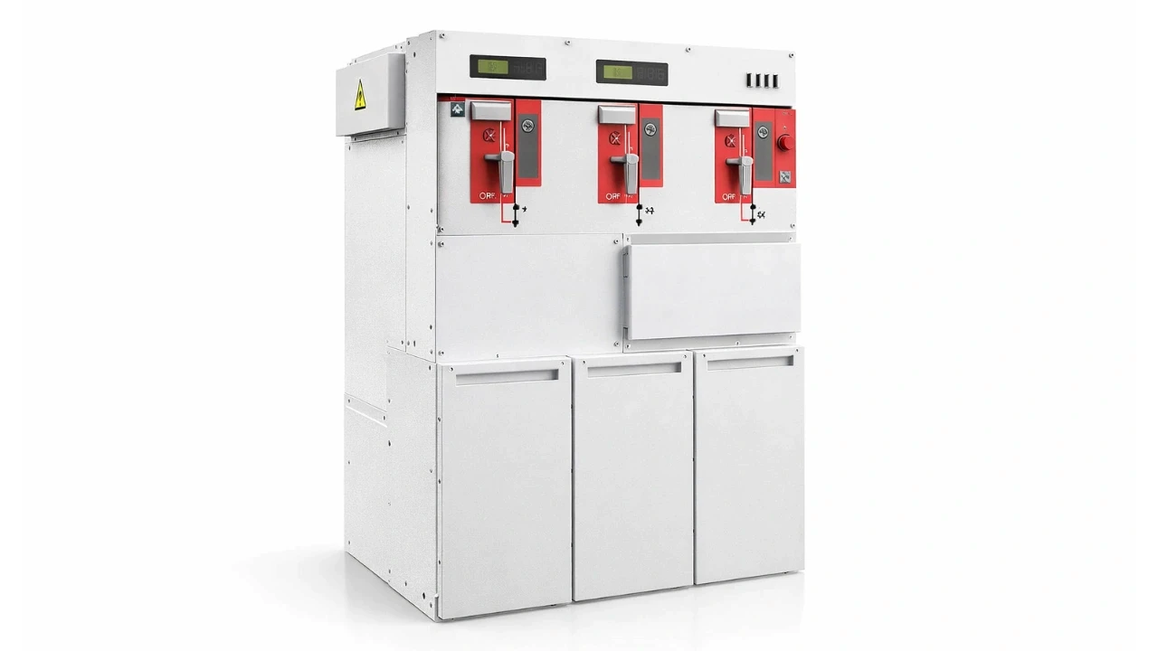
The location is not fixed, though. Ring main units place the low voltage devices in the upper section too, while in EHV GIS the compartment may hold HMIs, relays, and monitoring systems. Some manufacturers fit low voltage sections at both top and bottom. The layout depends on:
Project requirements
Customer preference
Protection requirements
Manufacturer design philosophy
That's why no two low voltage compartments look exactly alike — but the core components are nearly always the same.
What Supplies Power to the Low Voltage Compartment?
The low voltage compartment runs on three supply sources: an auxiliary DC supply, current transformers, and voltage transformers.
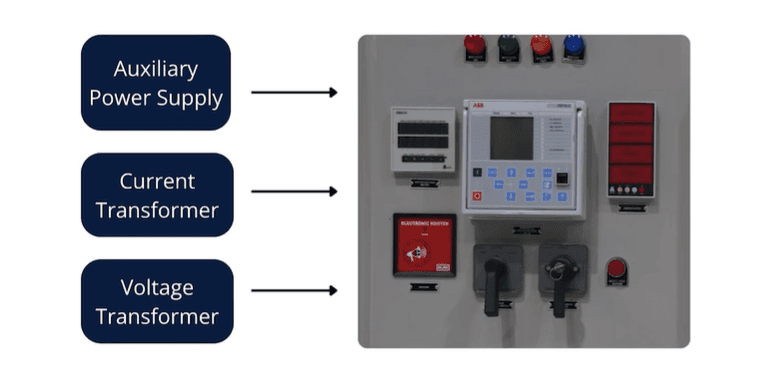
1. Auxiliary power supply. This feeds relays, indication lamps, annunciators, and control circuits. It usually comes from battery banks, auxiliary transformers, or a DC supply system — most commonly 110V DC or 220V DC.
2. Current transformer (CT). The CT steps the feeder current down to a safe value. If the incoming feeder carries 800A, the CT reduces it to 1A or 5A, which then feeds relays and meters.
3. Voltage transformer (VT). The VT steps system voltage down to safe levels such as 110V/√3 or 220V/√3, which feed voltmeters and voltage-based protection relays.
This is why CTs and VTs are critical to the whole switchgear system — without them, low voltage devices could not operate safely.
What Components Are Inside the Low Voltage Compartment?
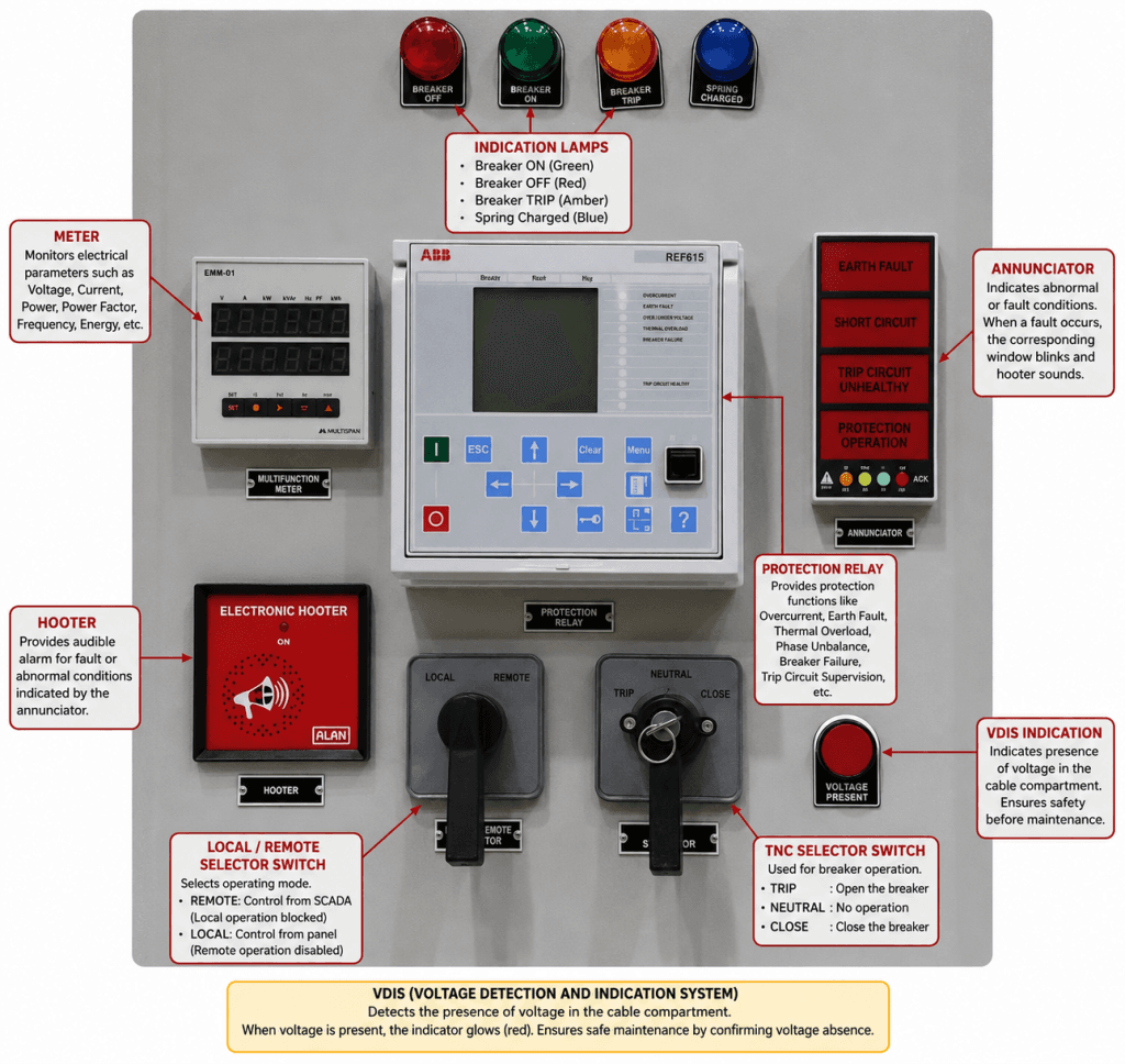
The low voltage compartment contains indication lamps, annunciators, meters, selector switches, protection relays, and a voltage detection system (VDIS). Each does a specific job.
Indication Lamps
Indication lamps show the operating status of equipment so operators can read switchgear conditions at a glance. Common indications include breaker ON, breaker OFF, breaker TRIP, spring charged, and trip circuit healthy. The signal comes from auxiliary switch contacts on the breaker mechanism — when the breaker position changes, the contacts change state and drive the lamp.
Annunciators
Annunciators indicate abnormal conditions, not normal status — that's the key difference from indication lamps.
Indication lamps | Annunciators | |
|---|---|---|
Shows | Normal equipment status | Faults and abnormal conditions |
Examples | Breaker ON/OFF, spring charged | Earth fault, short circuit, trip circuit unhealthy |
Behaviour | Steady on/off | Window blinks; may trigger a hooter |
When a fault occurs, the matching annunciator window blinks, and some systems add an audible hooter. The number of windows depends on project requirements.
Meters
Meters monitor electrical parameters continuously. Some panels use dedicated ammeters and voltmeters; others use multifunction meters that read voltage, current, power factor, active power, and reactive power. Some panels also include revenue meters for energy monitoring.
Selector Switches
Selector switches let operators choose an operating mode. The local/remote switch is the common one: in remote mode the breaker is controlled from SCADA and local operation is blocked; in local mode, remote commands are disabled. This also acts as a safety interlock. The other common one is the TNC switch — Trip, Neutral, Close — used for breaker operation.
Protection Relays
Protection relays are the most important devices in the compartment. A modern relay packs several functions into one unit, which may include:
Overcurrent protection
Earth fault protection
Thermal overload protection
Phase unbalance protection
Breaker failure protection
Trip circuit supervision
A single panel may carry more than one relay depending on protection needs. Switchgear of this class is governed by IEC 62271, the standard family for high-voltage (including MV) switchgear and controlgear.
Voltage Detection and Indication System (VDIS)
VDIS lets operators confirm whether voltage is present in the cable compartment before anyone works on it. Before touching a conductor, maintenance staff must verify there is no voltage — VDIS gives that indication. Once voltage absence is confirmed, work can begin safely. It's a core safety feature in MV systems and RMUs.
Why Does the Low Voltage Compartment Matter for Safe Operation?
It matters because it's the only part of the switchgear operators access routinely while the system is live.
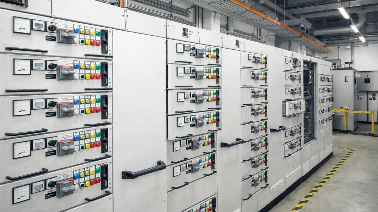
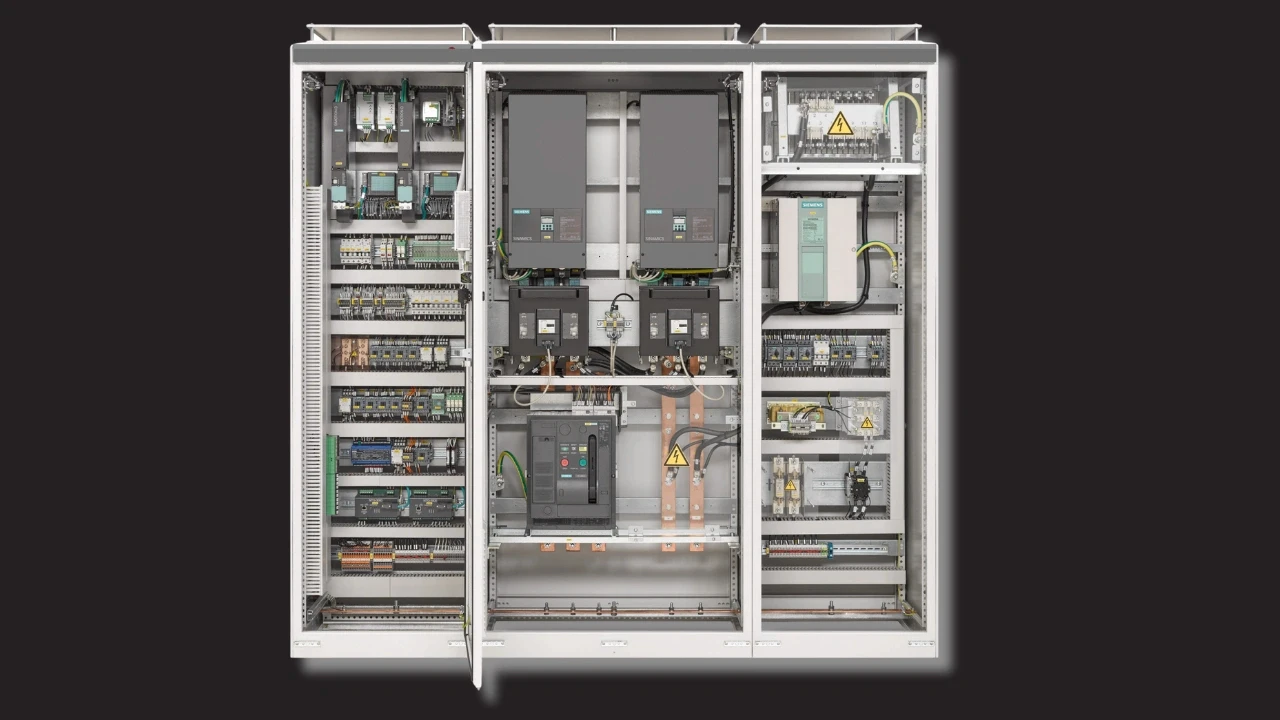
Staff don't open the cable or breaker compartments on an energized system. But they constantly use the low voltage side to check indications, monitor relays, perform local operation, review alarms, and reset faults. Open the compartment internally and you'll see a dense bundle of wires and logic circuits — and as more protection functions and interlocks are added, both the wiring complexity and the panel cost go up, because you need more wires, MCBs, contactors, relays, and interlocking circuits. Without a well-designed low voltage compartment, safe operation and protection simply aren't possible.
FAQ
What voltage does the low voltage compartment operate at?
Below 1000V. It typically uses an auxiliary DC supply of 110V DC or 220V DC (sometimes 48V DC), with CTs and VTs stepping system values down to safe levels.
What's the difference between an indication lamp and an annunciator?
Indication lamps show normal status (breaker ON/OFF, spring charged). Annunciators flag abnormal conditions (earth fault, short circuit, trip circuit unhealthy) and usually blink, sometimes with an audible hooter.
What is VDIS used for?
The Voltage Detection and Indication System confirms whether voltage is present in the cable compartment, so maintenance staff can verify a section is dead before working on it.
Why are CTs and VTs needed inside switchgear?
Relays and meters cannot sit directly on 36kV. CTs step current down (e.g. 800A to 1A or 5A) and VTs step voltage down (e.g. 110V/√3), so low voltage devices can operate safely.
Conclusion
The low voltage compartment is the operational brain of MV switchgear — it manages protection, monitoring, indication, and breaker control while running safely below 1000V on CTs, VTs, and auxiliary supplies. Understand it, and you'll troubleshoot faster and operate switchgear more safely.
Watch the full video walkthrough to see a real low voltage compartment explained component by component.
Watch the Youtube Video

About Author
Gaurav Joshi
Gaurav started his career on the floor of the electrical industry — not in a classroom. Working across Siemens and Schneider Electric, he saw firsthand how wide the gap was between what colleges teach and what the industry actually needs.
So he did something about it.
Today, he's built a global community of 300,000+ engineers and professionals across YouTube and beyond — and TheElectricalGuy Academy is where that knowledge lives in its most structured, practical form.